
Wiring
Campervan Wiring Diagram and Step-by-Step Guide
A safe campervan layout starts at the house battery: Class-T main fuse, disconnect, positive bus, and a negative shunt before the negative bus. Solar and alternator charging feed the buses through their own controllers and fuses. DC loads leave through a fuse block, while the inverter gets a dedicated heavy cable and fuse.
- Fuse the wire: each positive conductor needs protection sized at or below its installed ampacity.
- Keep the inverter run short: high-current 12V cable gets large quickly.
- Get qualified review: permanent AC outlets, shore power, bonding, and code compliance are not beginner-only work.
Wiring a van for the first time feels intimidating, but the layout is logical: a battery in the middle, charging sources feeding in on one side, and your loads drawing out the other. This walkthrough explains each part and how it connects, in beginner-friendly language.
Campervan electrical wiring diagram
This original planning diagram shows the protected power paths and the order of the major components. It deliberately omits site-specific wire gauges and fuse values. Those depend on the equipment manual, continuous current, surge behavior, cable length, insulation rating, bundling, ambient temperature, and local requirements. It also omits chassis bonding, equipment grounding, AC protective devices, and shore-power wiring because those details depend on the inverter, charging equipment, vehicle, and applicable code. Do not use this drawing as a grounding or AC wiring plan.
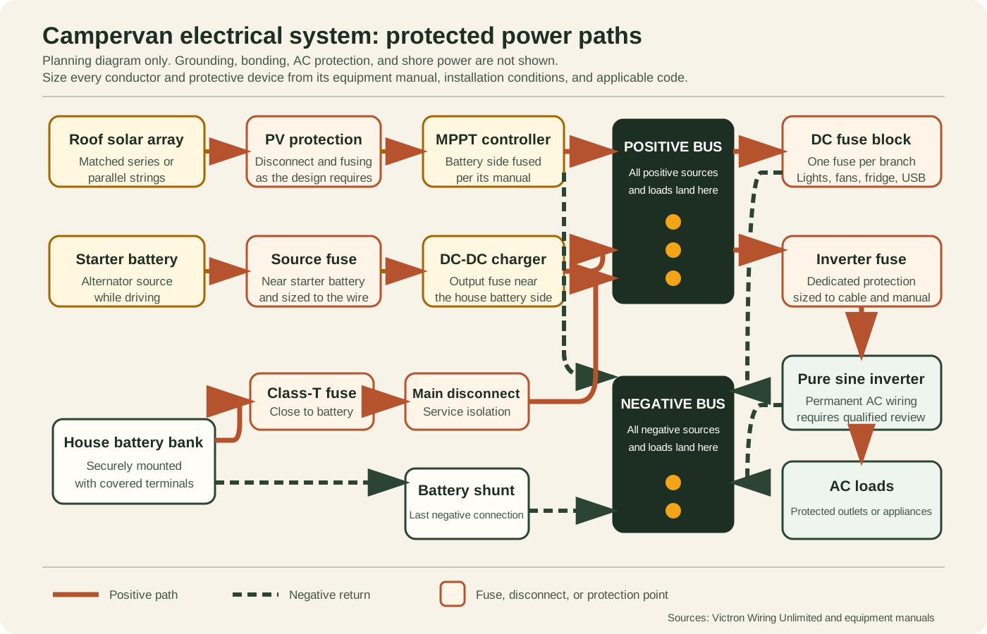
Download the printable SVG wiring diagram. Print at landscape orientation and keep it with the equipment manuals while laying out the system.
Diagram bill of materials
| Group | Components shown | What must be verified |
|---|---|---|
| Battery protection | House battery, Class-T fuse, disconnect, covered positive bus | Interrupt rating, fuse value, cable ampacity, terminal covers |
| Monitoring and return | Battery shunt and negative bus | All loads and chargers land on the system side of the shunt |
| Solar charging | Array, PV disconnect or protection, MPPT, battery-side fuse | String voltage, controller limits, conductor protection, disconnect rules |
| Alternator charging | Starter battery, source fuse, DC-DC charger, output fuse | Fuse both battery-fed ends according to the charger manual |
| Loads | DC fuse block and separately fused pure sine inverter | Branch fuses, inverter cable and fuse, AC protection and code review |
| Grounding and AC protection | Intentionally not shown | Equipment chassis, DC bonding, AC protective earth, shore power, and transfer switching require an equipment-specific, code-compliant design |
The mental model: power flows through the battery
Everything in a van system connects to the battery, but not directly. Charging sources (solar, the alternator) push power in, and loads (lights, fridge, inverter) pull power out. Between them sit two simple hubs called bus bars, one positive and one negative, plus fuses to protect every wire. Get that picture and the rest is just connecting parts in the right order.
The parts, from battery outward
1. The battery
A 12V LiFePO4 battery is the standard for vans. It is the bank that stores all your energy. Mount it securely so it cannot move while driving, and keep the terminals accessible.
2. Main fuse and battery shutoff
Right at the positive battery terminal, install a main fuse (often a Class T or ANL fuse) and a battery disconnect switch. The fuse protects the main cable, and the switch lets you kill all power for service or storage. This is your most important safety hardware.
3. Positive and negative bus bars
Run one heavy cable from the battery positive (through the main fuse) to a positive bus bar. If the system uses a battery monitor, run the battery negative to the battery side of its correctly rated shunt, then connect the shunt's system side to the negative bus. Every load, charger, and other system negative must land after the shunt. Now every other part connects to the bus bars instead of fighting for room on the battery terminals.
4. The charging sources
Two common ways to refill the battery:
- Solar: panels on the roof feed a charge controller (MPPT is standard), and the controller feeds the bus bars. Never wire panels straight to the battery. See our charge controllers guide.
- Alternator (DC-DC charger): a DC-DC charger takes power from the engine's starter battery while you drive and safely charges your house battery. It is the fastest way to refill on travel days.
5. The loads
Two kinds of loads pull from the bus bars:
- DC loads (lights, fridge, fans, USB, water pump) connect through a fused distribution block. Each circuit gets its own fuse sized to its wire.
- AC loads (laptop charger, blender, anything with a wall plug) run from an inverter, which converts battery DC into household AC. Choose pure sine wave.
The order to build it
- Mount the battery, main fuse, disconnect switch, and both bus bars. Leave the battery disconnected.
- Add the charge controller and wire it between panels and bus bars (panels last).
- Add the DC-DC charger if you are using alternator charging.
- Add the DC fuse block and wire your 12V loads, each on its own fuse.
- Add the inverter on its own heavy, fused cable to the bus bars.
- Double-check every fuse and connection, then connect the battery last.
Building in this order means the system is never live while you are still adding parts, which is far safer.
Recommended gear
The simplest way to avoid mismatched parts is to follow a proven parts list. Our Classic 400W RV and van build lists every component, the battery, MPPT controller, DC-DC charger, inverter, and a wiring kit, in compatible sizes, with the wiring order explained. For a smaller rig, see the minimalist van build, and to tailor it to your van use the Solar Calculator. Want the panel, controller, and roof wiring already matched in one box? Compare our campervan solar kit picks.
We may earn a commission from links on this page, at no extra cost to you. As an Amazon Associate we earn from qualifying purchases.
As a concrete example, these are the four core parts from that 400W build, already sized to work together:
- Solar: 2x Renogy 200W mono panels
Check Price on Amazon - Battery: 12V 200Ah LiFePO4 battery with a BMS rated for 200A
continuous discharge (many 200Ah units ship a 100A BMS, which cannot feed a 2000W
inverter; check the spec sheet)
Check Price on Amazon - Charge controller: Victron SmartSolar MPPT 100/30
Check Price on Amazon - Inverter: Renogy 2000W pure sine wave inverter
Check Price on Amazon
This is not a complete bill of materials. The main fuse, bus bars, disconnect switch, fuse block, and cable all still need to be sized to your wire runs and loads, exactly as covered above.
Commissioning checklist before the battery goes live
- Confirm the house battery is disconnected and every removable branch fuse is out.
- Trace positive and negative conductors against the diagram. Check polarity with a meter instead of relying on cable color alone.
- Confirm every fuse is appropriate for the protected wire and does not exceed the equipment manual's specified maximum.
- Verify cable lugs, bus bars, shunt, and equipment terminals are tightened to the manufacturer's torque specification and protected from accidental contact.
- Check for unintended continuity between the positive and negative buses. Follow the inverter manual's precharge procedure if it requires one.
- Connect the battery, close the main disconnect, and energize one branch at a time while watching for heat, odor, abnormal voltage drop, or fault indicators.
- Test charging sources separately before combining them, then verify the battery monitor sees both charge and discharge current in the correct direction.
Related guides
Choose your AC loads before sizing the cables. Our campervan inverter sizing guide connects appliance demand to continuous output, startup loads, and battery draw.
Engineering references
- Victron Energy: Wiring Unlimited, including DC fuses, disconnects, shunts, bus bars, mobile installations, and grounding.
- Blue Sea Systems: circuit protection and conductor-sizing case study.
- Off-Grid Field Guide DC wire gauge chart, with the formula, ampacity constraints, and worked inverter example used by this diagram.
Frequently Asked Questions
What order do I wire a campervan electrical system?
Build the battery and safety hardware first (battery, main fuse, bus bars, shutoff). Then add the charging sources (solar via the controller, and a DC-DC charger from the alternator). Then add the loads (a fuse block for DC devices and the inverter for AC). Connect the battery last, after everything else is in place.
Do I really need fuses everywhere?
Yes. A fuse protects the wire, not the device. Without one, a short can turn a battery cable into a fire starter in seconds. Every wire leaving the battery needs a fuse close to the battery, sized to the wire.
What are bus bars and why use them?
A bus bar is a single metal bar with several connection points. Instead of cramming many wires onto the battery terminals, you run one big cable to a positive bus bar and one to a negative bus bar, then connect everything else there. It is tidier, safer, and easier to service.
Can I wire 120V outlets in my van myself?
For low-voltage 12V DC work, careful beginners can do a lot themselves. But permanent 120V or 240V AC wiring, especially shore-power hookups, is where mistakes are dangerous and often must meet code. Have a licensed electrician handle or inspect that part.